






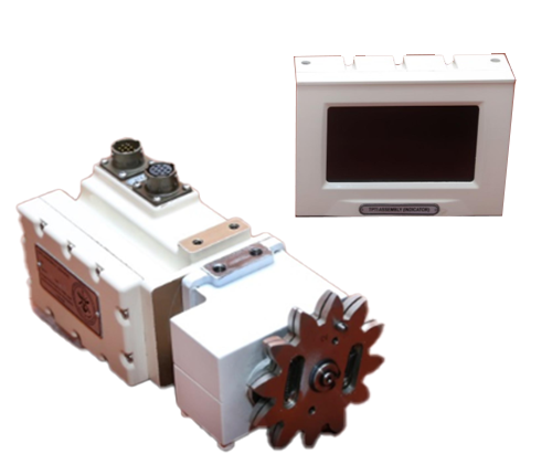
To replace the three systems configuration of ARJUN MARK ‘I’ Turret Position Transmitter and Indicator (TPTI) using Absolute Shaft Encoder has been developed. The system is intended to convert the existing analog system into digital system and introduces CAN Bus for ease of connectivity in the Mark II version of ARJUN Tanks.
Other Specifications can also be achieved depending on Customer Requirements.
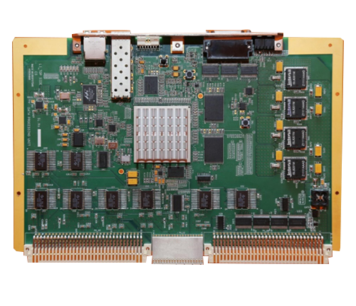
The Data Processing Unit FPGA based embedded system designed and developed for processing the raw information from the front end Receiver to a 128bit Signal Descriptor Word. The processed signal descriptor word is transmitted to host controller in 27.4ns on optical fiber link @ 3.125Gbps. The card is enclosed in a Conduction Cooled Mechanical enclosure specifically fabricated as per the customer requirement, meeting all the requirements of VITA 46 Standards.
Other Specifications can also be achieved depending on Customer Requirements.
The Receiver processor unit accepts the pulse to pulse data (like Frequency, Pulse width, Amplitude, Direction of Arrival, time of Arrival etc.) measured by an ESM receiver and converts them into a time synchronous 128 bit data organized as 32bits x 4words. This board forms the interface between the receiver processor output and ESM processor input. The 32 bit x 4word data is interfaced to a high speed fiber optic cable (using a parallel to serial data converter) for onward transmission to an ESM processor. The maximum shadow time for transmitting the data for one pulse is <200ns (excluding the length of the fiber optic cable).
Other Specifications can also be achieved depending on Customer Requirements.
The Receiver processor unit accepts the pulse to pulse data (like Frequency, Pulse width, Amplitude, Direction of Arrival, time of Arrival etc.) measured by an ESM receiver and converts them into a time synchronous 128 bit data organized as 32bits x 4words. This board forms the interface between the receiver processor output and ESM processor input. The 32 bit x 4word data is interfaced to a high speed fiber optic cable (using a parallel to serial data converter) for onward transmission to an ESM processor. The maximum shadow time for transmitting the data for one pulse is <200ns (excluding the length of the fiber optic cable).
Other Specifications can also be achieved depending on Customer Requirements.
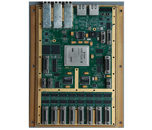
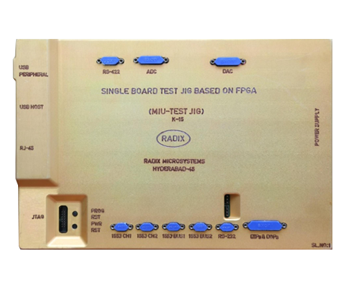
The Automated Test-jig for Avionics unit is Virtex–5 FPGA based embedded system designed and developed for simultaneously testing four Avionic sub-systems with MIL-STD-1553 interfaces. The system is ported with Embedded Linux (Kernel 3.4), A multi-tasking algorithm has been developed to test the avionic sub-systems. The table top Automated Test-Jig for Avionics board is enclosed in a mechanical enclosure specifically fabricated asper the customer requirement to comply with full ESS specifications.
Other Specifications can also be achieved depending on Customer Requirements.